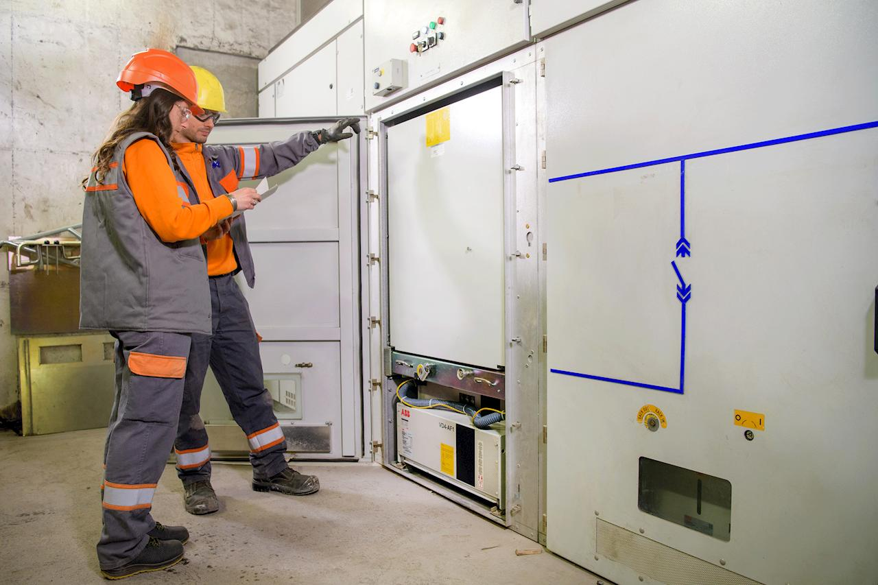
Electrical distribution networks rely on equipment that can control, protect, and isolate circuits under normal operating conditions and during faults. Among this equipment, switch gear systems are used in substations, industrial facilities, commercial buildings, utility networks, and other installations where electrical power must be managed safely.
A switchgear assembly may contain circuit breakers, disconnect switches, fuses, protective relays, busbars, and control components. These parts work together to interrupt fault currents, isolate equipment for maintenance, and direct electrical power through different sections of a distribution system.
What Switchgear Does in an Electrical Network
Electrical systems can experience short circuits, overloads, equipment failures, and other abnormal conditions. Without suitable protection, these events can damage transformers, cables, motors, generators, and other costly components.
Switchgear provides a controlled point for managing electrical circuits. A circuit breaker, for example, can open a circuit when a protective relay detects an abnormal current. Disconnecting equipment also allows technicians to isolate a section of the network before inspection or repair.
The equipment is selected according to factors such as system voltage, fault-current rating, installation environment, available space, operating requirements, and applicable electrical standards.
See also: Korea to Indonesia: Your Ultimate Asia Escape Guide
Medium-Voltage Applications and Equipment Selection
Medium voltage switchgear is commonly used in electrical systems serving industrial plants, commercial facilities, utility distribution networks, and large infrastructure projects. Medium-voltage equipment generally operates above low-voltage distribution levels but below high-voltage transmission equipment.
The assembly can include vacuum circuit breakers, protection relays, busbars, current transformers, voltage transformers, and disconnecting mechanisms. Vacuum circuit breakers are widely used because they can interrupt fault currents without relying on oil as the interrupting medium.
Engineers must consider the rated voltage, continuous current, short-circuit withstand capability, insulation requirements, and environmental conditions before selecting equipment. Available installation space and future expansion requirements can also influence the design.
How Gas Insulated Designs Differ
Space can be a major concern in substations and industrial facilities. Gas insulated switchgear uses an insulating gas within sealed compartments to provide electrical insulation between energized components.
Compared with conventional air-insulated arrangements, gas-insulated designs can occupy considerably less space. The enclosed construction also reduces exposure of internal conductors to dust, humidity, salt deposits, and other environmental contaminants.
The design is often considered for urban substations, industrial installations, transportation infrastructure, and locations where land availability is limited. Installation and maintenance requirements differ from those of conventional equipment, so the surrounding electrical system and service capabilities should be considered during project planning.
Why Enclosures Matter
A switchgear assembly must provide suitable protection for energized electrical components while allowing authorized personnel to operate and service the equipment safely. Metal enclosed switchgear uses a metal enclosure to contain electrical components and provide physical separation from surrounding areas.
The enclosure can help protect internal equipment from accidental contact and environmental exposure. Depending on the design, compartments may separate busbars, circuit breakers, cable connections, and other components.
Proper compartmentalization also affects maintenance procedures. Technicians need to know which sections remain energized and which sections have been isolated before beginning work. Equipment labels, interlocks, grounding provisions, and access arrangements therefore form an important part of the overall installation.
Components Found Inside a Switchgear Assembly
Although designs vary, several components appear frequently across different switchgear installations.
Circuit breakers: These devices interrupt electrical current during faults and can also be operated under specified normal switching conditions.
Disconnect switches: Disconnectors provide visible or defined isolation points, depending on the equipment design and applicable standards.
Protective relays: Relays monitor electrical conditions such as current, voltage, frequency, and other parameters. When abnormal conditions meet programmed settings, the relay can initiate a trip command.
Busbars: Busbars provide a common electrical connection between incoming and outgoing circuits within the switchgear assembly.
Current and voltage transformers: Instrument transformers reduce electrical quantities to levels suitable for measurement and protection equipment.
Grounding equipment: Grounding provisions help establish a safe path for fault current and support safe maintenance procedures.
The coordination of these components determines how effectively a switchgear installation responds to abnormal electrical conditions.
Operating Conditions Affect Equipment Life
Electrical equipment does not operate in isolation. Temperature, humidity, dust, vibration, switching frequency, load levels, and fault exposure can influence its condition over time.
A circuit breaker that operates frequently may experience mechanical wear. Connections can loosen or develop excessive resistance. Insulation can deteriorate because of heat, contamination, moisture, or electrical stress.
For this reason, equipment condition should be considered throughout its service life rather than only after a failure occurs.
Maintenance Tasks That Support Reliable Operation
Switchgear maintenance can involve visual inspections, mechanical checks, electrical testing, cleaning, lubrication where specified by the manufacturer, connection inspections, and verification of protective devices.
Technicians may inspect insulation surfaces for contamination or damage, examine cable terminations, check mechanical operating mechanisms, and test circuit-breaker performance. Protective relay settings may also be reviewed against approved coordination studies and system requirements.
Testing methods depend on the equipment type and manufacturer instructions. Some installations may require insulation-resistance testing, contact-resistance measurements, breaker timing tests, relay testing, or other specialized procedures.
Maintenance intervals should be based on manufacturer recommendations, operating conditions, equipment age, duty cycle, and applicable standards. A facility with frequent switching operations or harsh environmental exposure may require closer attention than equipment operating under lighter conditions.
Safety Before Inspection or Repair
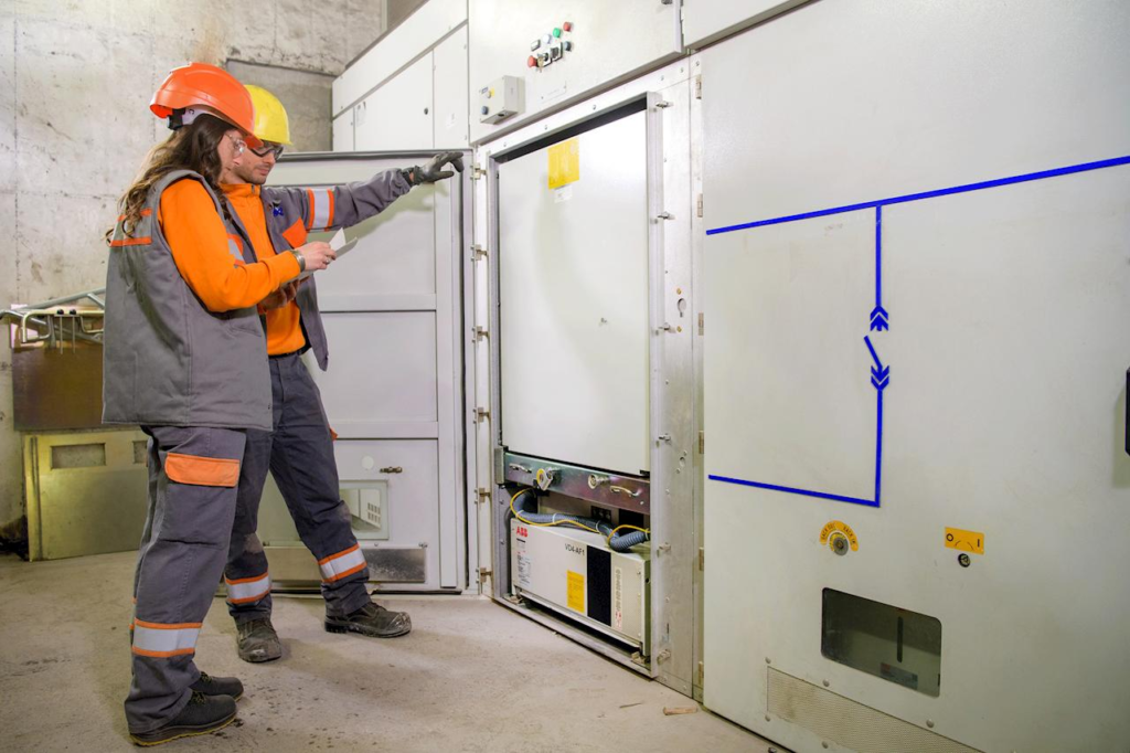
Work on switchgear requires careful control of electrical hazards. Authorized personnel should follow the facility’s electrical safety procedures and applicable regulations.
Before maintenance begins, workers generally need to identify the correct equipment, isolate the relevant circuit, verify the absence of voltage using appropriate methods, apply grounding procedures where required, and control access to the work area.
Interlocks and warning labels should never be bypassed without an approved procedure. Equipment that appears inactive may still contain stored electrical energy or have energized sections connected through another circuit.
Detailed switching procedures and documented isolation steps reduce the chance of an incorrect operation during maintenance.
Choosing a Suitable Configuration
The right switchgear arrangement depends on the electrical network rather than on a single equipment feature. Engineers typically examine voltage level, current demand, prospective fault current, environmental conditions, physical space, protection requirements, maintenance access, and future load growth.
Air-insulated and gas-insulated arrangements have different physical and operational characteristics. Metal-enclosed designs can provide a different level of compartmentalization and protection from open electrical arrangements. Circuit-breaker technology also varies according to voltage class and application.
Project specifications should therefore be developed around the actual electrical conditions and applicable standards. Manufacturer documentation is equally important because ratings, maintenance procedures, and operating limitations vary between equipment models.
Keeping Electrical Distribution Equipment Serviceable
A well-planned switchgear installation provides more than a means of turning circuits on and off. It creates controlled points for protection, isolation, measurement, and electrical distribution.
Regular inspections, suitable protection settings, correct operating procedures, and maintenance records can help identify developing equipment problems before they interrupt a facility’s electrical service. Selection should begin with the network’s technical requirements, followed by consideration of space, environmental conditions, safety provisions, and long-term service needs.
Understanding how switch gear systems are constructed and operated gives facility managers, engineers, and maintenance teams a clearer basis for evaluating electrical distribution equipment and planning its service throughout its operating life.